How do PCBs Work?
That smartphone your holding has over 110 meters or about 360 feet of wires inside of it. That’s what it takes to combine a camera, speaker, display, wifi, antenna, GPS, battery, fingerprint sensors, dozens of microchips, and many more components, into a single device and have all the components work seamlessly together.
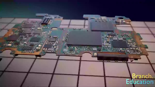
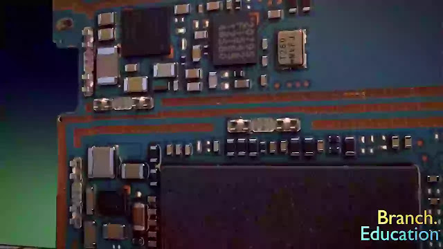
There is one football field's length of wire that fits rather comfortably in that smartphone of yours. But wait, where are all of these wires? Enter the printed circuit board or PCB. You’ve probably seen a circuit board like this one and it might have been green- not blue but, what you may not know is this circuit board is really a multilayered labyrinth of hundreds of copper wires.
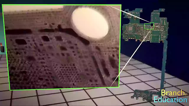
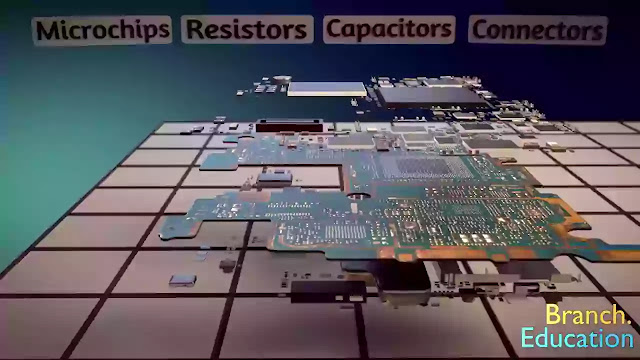
This PCB provides structure and organization for all the components to be mounted on the surface, while wires in the middle allow each of the components to communicate and work together. So, then what’s inside the printed circuit board and how does it work? First, let’s establish the difference between components such as the microchips, resistors, capacitors, connectors, and the printed circuit board itself. These are the components, and they are solder mounted or attached to the PCB. The term motherboard refers to a printed circuit board with the components mounted to it, whereas a PCB is just a flat board without anything on it. Certain components like the display and camera are not mounted directly to the PCB, but rather they are attached to the PCB through a set of mating connectors and a flat cable. This is an X-Ray picture I had taken of this PCB.
What are PCBs? || How do PCBs Work?
The dark areas are the conductive wires or traces and there are a lot of them, The dark areas are the conductive wires or traces and there are a lot of them, and the rest of the material is a non-conductive insulator. and the rest of the material is a non-conductive insulator. made of woven fiberglass with an epoxy resin binder called FR4. In this x-ray image, you can see multiple layers of wires, all on top of each other, but they are not actually touching.
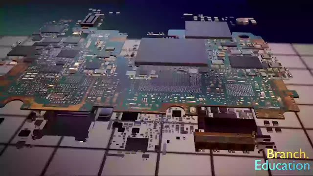
Okay, let’s move on. Here is the main microchip on the smartphone. It’s called the System on a Chip or SoC for short and it’s mounted onto the PCB on a grid of connection points or pads called a ball grid array, thereby connecting the brain of the smartphone to the wires or traces, that run through the PCB. There are many other pads on the PCB for the other microchips, such as the memory chip and wireless chip, as well as resistors, capacitors, and other components. Let's focus on a small set of wires These 15 traces connect the SoC to the 16 megapixel back camera, whereas these 10 traces connect the SoC to the 5-megapixel front camera.
The higher number of traces allows for more data to be sent. Note that each of these traces is electrically separate and cannot touch any other trace. Here we have these 32 wires that are routed along the edge of the printed circuit board and connected to a flat cable that goes to the touchscreen display. All these tiny signal wires must be routed through the PCB and fit within a width of less than 1 millimeter. In summary, the PCB or Printed Circuit Board allows each of the components to communicate with the System on a Chip or SoC and other microchips via hundreds of wires and rather precise organization.
What are PCBs? || How do PCBs Work?
So then, what is the Printed Circuit Board made of? Well, this smartphone’s PCB is actually built of 10 conductive layers.
Let’s go through them quickly. The top and bottom layers are used for mounting components and acting as multiple antennae. Also, each of these components on the circuit board needs power and ground and the PCB has entire layers that are dedicated to just that and are aptly named the power planes and the ground planes. Additional ground planes are also used for electromagnetic shielding and heat dissipation.
The remaining 4 middle layers are used to carry all the communication traces or signal wires. Each of the conductive layers is composed of copper, and between each of the layers is insulating fiberglass and epoxy resin that prevents the flow of electricity. This PCB has 10 conductive layers, however, in other applications, they can have anywhere from 2 to 50 or more layers! But most PCBs stay around 2 to 10. Additionally, on the top and bottom is a coat of colored solder masks, which provides electrical insulation while keeping the mounting pads for the components accessible. And on top of that, is the silkscreen, which is just ink used for markings and letters that tell where components are placed.
Let's jump out of animation. Hi, I'm Teddy, and I’m the creator behind Branch Education. Let’s take a short break from all this technical jargon and slow down and chat. I think it’s truly amazing that 50 years ago computers took up entire rooms and looked like this, and now, after decades of really hard engineering and development, we have something this light, small, thousands of times more powerful, and everyone has one of these in their pocket! Our world is amazing! but these innovations were only made possible because of the hundreds of thousands of scientists, mathematicians, and engineers that studied hard and then worked even harder to discover, and design transistors, microchips, and PCBs, while shrinking the size of each one of these by factors of multiple thousands.
So, here’s my pitch: If you want a future full of even more amazing innovations, then you should take it onto yourself and pursue a career in science, technology, math, or engineering! But, if you can't do that, another way you help us by liking and then sharing this video, and maybe it will inspire some student out there to pursue science, technology, engineering, or mathematics career themselves, and then they will work towards a future of amazing innovations. Hit this like a button here, and then this one here and share this video with others.
Thanks for watching and helping out! Ok, now let’s get back to the PCB and the thousands of microscopic wires inside of it. So where were we: ok. with 10 separate conductive copper layers and insulating material between each layer, how do signals travel from one layer to another? Well, vias or vertical interconnect accesses perform this function. You can see them in the x-rays here. Vias are drilled and metal-plated holes that connect two or more layers. There are three types of vias: through vias are holes that go from the top to the bottom layer. Blind vias connect either the top or bottom layer to a middle layer and buried vias connect internal layers to one another.
Because vias can pass through multiple layers, when they pass through a layer that they don't want to connect to, the copper is removed from around the via on that layer. Let’s take another look at an X-Ray of a very small portion of this PCB, and then let’s zoom in even further on this X-Ray. Here are the pads on the top side of the PCB for mounting components, and on the inside you can see a set of wires running this direction, and then another set of wires running perpendicular to that direction on a separate layer, and a third set of wires at an angle, while vias go between each layer.
Here's a dime so that you can get a sense of scale for the size of these wires. These intricate wires found inside the PCB at the center of your Smartphone are just mind-blowing. Okay, let’s move on, each model of smartphone is different in shape and specifications, and thus each has a different Printed Circuit Board, which engineers carefully design. For example, some smartphones separate the top and bottom PCBs, with the bigger one called the motherboard and the smaller, the daughterboard. Or, for another example, some newer smartphones stack PCBs on top of one another in order to fit more space for a larger battery and more cameras. Another important detail is that this PCB is light and small- it weighs just shy of a tablespoon of water, and well, it fits inside your smartphone.
What are PCBs? || How do PCBs Work?
Engineers have been continuously innovating; making microchips, resistors, capacitors, inductors, and connectors as small as possible- some of these components are smaller than a flea. Older designs of PCBs used components that took up much more space both on the board and through the board. Due to their mounting mechanism as a leg going through a hole, these older designs were called through-hole components. However, these components here are all surface mount devices or SMD and engineers are continuously developing smaller and lighter solutions. Through Hole, Blind Via, Buried Via
I’m telling you- one of you will the engineer to design the next generation of electronics. So let’s summarize and wrap this article up: Printed Circuit Boards are integral in all electronics. and they come in a whole variety of shapes and designs. They provide structure, nice neat, organized homes for all the components, and they also connect the components using a vast labyrinth of over 100 meters of wires in a connect the dots like fashion. That's about it for this post. Thank you for reading! Consider subscribing, and if you learned something new, make sure to hit that like button, but more importantly share this video with others and hopefully, it will reach the student or more likely a group of students who will invent the next breakthrough technology in electronics! This article branches to PCB Manufacturing, PCB Design, And all the components that get mounted onto the PCB Such as the System on a Chip and the solid-state drive. Ask questions in the comments, and until next time consider the conceptual simplicity yet structural complexity in the world around us.
